Automotive Transformation
Smart car and data center-on-wheels are just some of the terms being used to define the exciting new waves of technology transforming the automotive industry and promising safer, greener self-driving cars and enhanced user experiences.
Underpinning it all is a megatrend towards software-defined vehicles (SDV). SDV is not just a new automotive technology platform. It also enables a new business model for automotive OEMs (original equipment manufacturers). With a software-centric architecture, car makers will have an innovation platform to generate unprecedented streams of revenue from aftermarket services and new applications. For owners, the capability to receive over-the-air software updates for vehicles already on the road – as easily as smartphones are updated – means an automobile whose utility will no longer decline over time and driving experiences that can be continuously improved.
The Road to SDV is Paved with Ethernet
A key technology to enable SDVs is a computing platform that is supported by an Ethernet-based in-vehicle network (IVN). An Ethernet-based IVN provides the ability to reshape the traffic between every system in the car to help meet the requirements of newly downloaded applications. To gain the full potential of Ethernet-based IVNs, the nodes within the car will need to “talk” Ethernet. This includes devices such as car sensors and cameras.
In this blog, we discuss the characteristics and main components that will drive the creation of this advanced Ethernet-based IVN, which will enable this new era of SDV.
First, let’s talk about the promises of this new business model. For example, people might ask, “how many new applications can possibly be created for cars and who will use them?” This is probably the same question that was asked when Apple created the original App Store, which started with dozens of new apps, and now, of course, the rest is history. We can definitely learn from this model. Plus, this is not going to be just an OEM play. Once SDV cars are on the road, we should expect the emergence of new companies that will develop for the OEMs a whole new world of car applications that will be aligned with other megatrends like smart city, mobility-as-a-service (MaaS), ride-hailing, and many others.
A New Era of Automotive Innovation
Let us now fast forward to the years 2025 to 2030 (which in the automotive industry is considered ‘just around the corner.’) New cars that are designed to support a higher level of advanced driver assistance systems (ADAS) include anywhere between 20 to 30 sensors (camera, radar, lidar, and others). Let’s imagine two applications that could utilize these sensors:
- Application 1: “Catch the Car Scratcher” – How many times have we heard of, or even been in, this situation? Someone scratches your car in the parking lot or maliciously “keys” your car. What if the car were able to capture the face of the person or the license plate number of the car that caused the damage? Wouldn’t that be a cool feature an OEM could provide to the car owner on demand? If priced right, it could become a popular application. The application would use accelerometers, and potentially a microphone, to detect noise associated with scratching, bumping, or hitting the car. Once the car identified the scratching or bumping, it would activate all the cameras around the car. The car would then record the video streams into central storage. This video could later be used by the owner to recover repair costs through insurance or the courts.
- Application 2: “Break-in Attempt Recording” – In this application, when the system detects a break-in attempt, all internal and external cameras record the video into central storage and immediately upload it to the cloud. This would be done in case the car thief tries to tamper with the storage later. In parallel, the user would receive a warning signal or alert by phone, enabling them to watch the video streams or even connect to the sound system in the car and scare the thief with their own voice.
Software-Defined Network
Ethernet network standards comprise a long list of features and solutions that have been developed over the years to address real network needs, including the mitigation of security threats. Ethernet was initially adopted by the automotive industry in 2014 and it has since become the dominant network in the car.
Once the car’s processors, sensors, cameras, and other devices are connected to each other via Ethernet (Ethernet end-to-end), we can realize the biggest promise of SDV: the capability to reprogram the in-vehicle network and adapt its main characteristics to new advanced applications. This capability is called in-vehicle software-defined Networking, or in short, in-vehicle SDN.
Figure 1 shows the building blocks for In-Vehicle SDN that enable SDV.
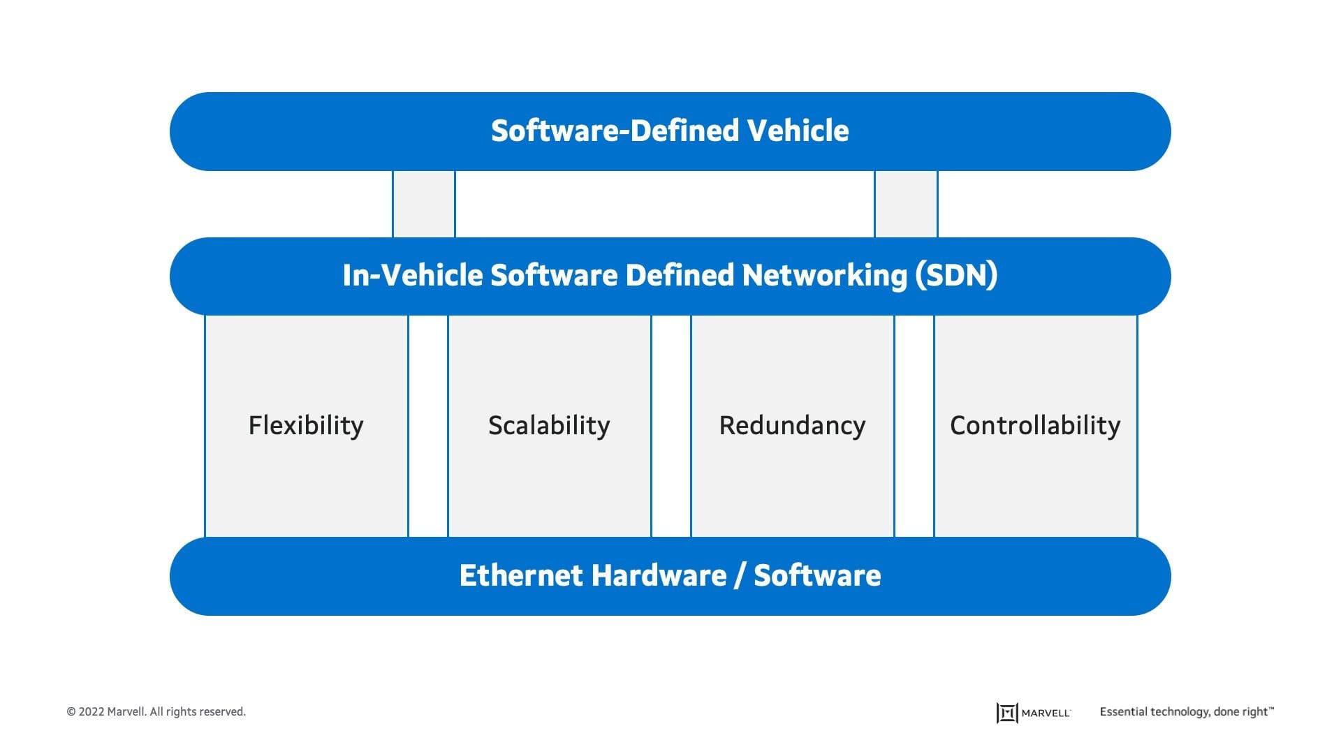
Figure 1 – Ethernet and SDN as building blocks for SDV
Ethernet features enable four key attributes that are key for SDV: flexibility, scalability, redundancy, and controllability.
- Flexibility provides for the ability to change data flow in the network and share devices (like cameras and sensors) between domains, processors, and other shared resources (e.g., storage).
- Scalability of both software and hardware is needed to support new applications and features. Software updates to the originally installed processors and electronic control units (ECUs) usually require changes in the network’s routing of data and controls. Hardware can be also modified over time in the car, and in many cases, adaptations to the network may be required to support new speeds and quality of service (QoS), for the new hardware.
- Redundancy, not only in mission-critical processors but also in data paths between the devices, safeguards the network. Switching and multi-data paths can also assist load balancing in the backbone of the in-vehicle network.
- Controllability, diagnostic, and real-time debugging of all links in the car provides real-time self-diagnosis and fault management, such as channel quality, link marginality/degradation, and EMC vulnerability, by leveraging the Ethernet’s operations, administration, and maintenance (OAM) protocol. With advanced, AI/ML based data processing, more effective prediction of network health is possible, enabling higher-level safety goals and significant economic benefits.
In-Vehicle SDN is the mechanism that provides the ability to modify and adapt these attributes in SDV. SDN is a technology that uses application programming interfaces (APIs) to communicate with underlying hardware infrastructure, like switches and bridges, and provisions traffic flow in a network. The In-Vehicle SDN allows the separation of control and data planes and brings network programmability to the realm of advanced data forwarding mechanisms in automotive networks.
Cameras and the Ethernet Edge
To realize the full capability of in-vehicle SDN, most devices in the car will need to be connected via Ethernet. In today’s advanced car architectures, the backbone of high-speed links is all Ethernet. However, camera interfaces are still based on old proprietary point-to-point low-voltage differential signaling (LVDS) technology. Newer technologies (like MIPI A-PHY and ASA) are under development to replace LVDS, but these are still point-to-point solutions. In this blog, we refer to all these solutions as P2PP (point-to-point protocol). In Figure 2, we show an example of a typical zonal car network with a focus on two domains that use camera sensors: ADAS and infotainment.
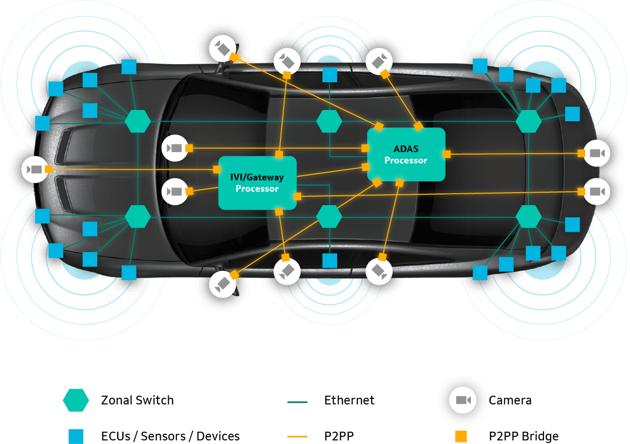
Figure 2 – Zonal network architecture with point-to-point camera links
While most of the ECUs/sensors/devices are connected through (and leverage the benefits of) the zonal backbone, cameras are still connected directly (point-to-point) to the processors. Cameras cannot be shared in a simple manner between the two domains (ADAS and IVI), that in many cases are in separate boxes. There is no scalability in this rigid connectivity. Redundancy is also very limited, since the cameras are connected directly to a processor, and any malfunction in this processor might result in a lost connection to the cameras.
One potential “solution” for this is to connect the cameras to the zonal switches via P2PP, as shown in Figure 3.
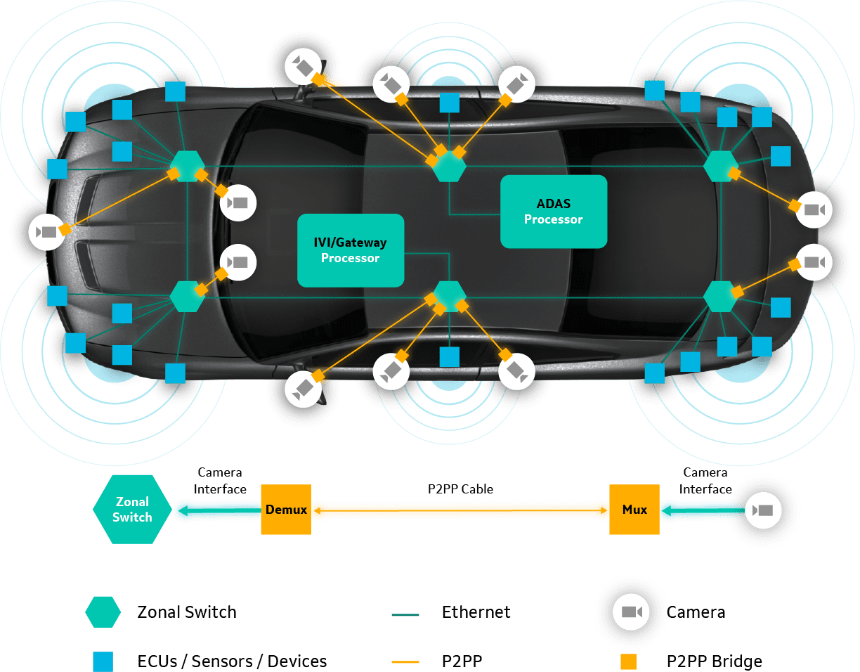
Figure 3 – Zonal network architecture with point-to-point camera links to zonal switch
This proposal solves only a few of the problems mentioned above but comes at a high cost. To support this configuration the system always needs a dedicated demux chip, as shown in Figure 4, that converts the P2PP back to the camera interface. In addition, to support this configuration, the zonal switches need a dedicated video interface, like MIPI D-PHY. This interface requires 12 pins per camera (4 pairs for data, 1 pair for clock, and 1 pair for control (I2C or SPI). This adds complexity and many dedicated pins which increases system cost. Another option is to use an external demux-switch (on top of the zonal switch) to aggregate multiple P2PP lanes, which is expensive.
Integration of any of these protocols into the zonal switch is also highly unlikely, since it requires dedicated, non-Ethernet ports on the switch. In addition, no one will consider the integration of proprietary or new and non-matured technologies into switches or systems-on-chip (SoCs).

Figure 4 – Camera P2PP bridge in zonal architecture
Next is controllability, diagnostics, and real-time debugging that do not work over the P2PP links in the same simple and standard way they work over Ethernet. This limits the leverage of existing Ethernet-based SW utilities that are used to access, monitor, and debug all Ethernet-based ECUs, devices, and sensors in the vehicle.
Ethernet Camera Bridge
The right solution for all these issues is to convert the camera video to Ethernet – at the edge. A simple bridge device that connects to the camera module and encapsulates the video over Ethernet packets is all it takes, as shown in Figure 5.
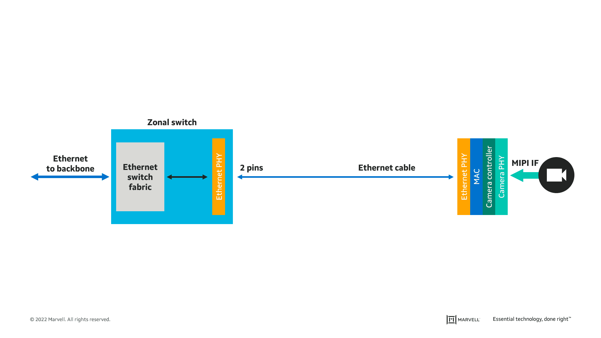
Figure 5 – Ethernet camera bridge in zonal architecture
Since the in-vehicle Ethernet network is Layer 2 (L2)-based, the encapsulation of camera video over Ethernet requires a simple, hard-coded (meaning no SW) media access control (MAC) block in the bridge device. Figure 6 shows a network that utilizes such bridge devices.
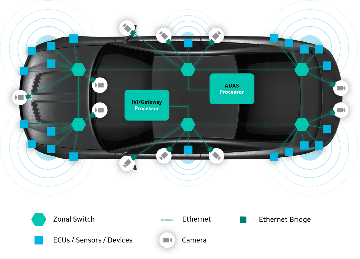
Figure 6 – Zonal architecture with Ethernet end-to-end
The biggest advantage of the Ethernet camera bridge is that it leverages the robustness and maturity of the Ethernet standard. For the Ethernet bridge physical layer (PHY) it means a proven technology (2.5G/5G/10GBASE-T1 and soon 25GBASE-T1) with a strong ecosystem of cables, connectors, and test facilities (compliance, interoperability, EMC, etc.) that have been accepted by the automotive industry for many years.
But this is only the tip of the iceberg. Once the underlying technology for the camera interface is Ethernet, these links automatically gain access to all the other IEEE Ethernet standards, such as:
- Switching and virtualization – IEEE 802.1™
- Security – authentication and encryption – IEEE 802.1AE™
- Time-Synchronization over network – IEEE 1588™
- Power over cable – IEEE 802.3bu™
- Audio/Video Bridging – IEEE 802.1BA™
- Asymmetrical transmission, using Energy Efficient Ethernet protocol – IEEE 802.3az™
The Ethernet end-to-end with Ethernet camera bridges supports all four key attributes (described in Figure 1) that are required for reliable software-defined car operation: Cameras can easily be shared among domains. Software and hardware can be easily modified independently and scaled all the way up to the camera and sensors. No special video interfaces are needed in the zonal switch – the camera Ethernet link is connected to a standard Ethernet port on the switch, and can be routed on multiple paths for redundancy. This approach offers the full support of controllability, diagnostic and real-time debugging of the camera links using standard Ethernet utilities that are used in the rest of the in-vehicle network.
At the 2022 Ethernet & IP @ Automotive Technology Day held in Yokohama, Japan, Marvell demonstrated this exciting new product category in a real-world scenario.
In the demo, a Marvell Ethernet camera bridge translated live, high-resolution camera video using the MIPI Camera Serial Interface (CSI-2) PHY transmission protocol that was converted and encapsulated over a 10 gigabit Ethernet (10GBASE-T1) MAC and PHY. Traffic flowed from the camera bridge to a Marvell automotive Ethernet switch; then over an automotive cable (10GBASE-T1) to a second Marvell switch connected to a graphics processing unit (GPU) bridge. The GPU bridge extracted the video from the Ethernet packets and displayed it on a monitor. The demonstration showed that existing cameras can be easily integrated into the Ethernet in-vehicle network, with no changes required to the camera equipment or protocols.
So, what’s next? As camera resolutions and refresh rates increase, camera links will need to support future data rates that climb beyond 10 Gbps. To support this trend, the IEEE P802.3cy™ Greater than 10 Gb/s Electrical Automotive Ethernet Task Force is already in the process of defining a standard for 25 Gbps automotive PHY. Therefore, we can expect the vehicle backbone as well as camera Ethernet bridges of up to 25 Gbps to be inevitable in the future, and with them, a plethora of even more compelling smart car apps.
Learn more about:
- How Marvell is committed to enabling smarter, safer, and greener vehicles with its innovative, end-to-end portfolio of Brightlane™ automotive solutions.
Authors:
- Amir Bar-Niv, vice president of marketing, Automotive Business Unit, Marvell


